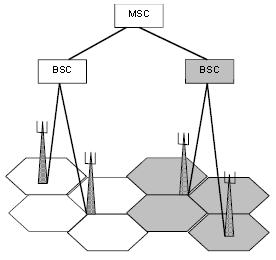
The geographical area to be covered by the Radio Network is divided into cells. A cell is the area covered by a set of frequencies (transceivers). Each cell has at least one control channel (for BCCH, PCH, SDCCH, etc)
1. Type of Cells
There are two main types of cells: omni-cell and sector-cell
- An omni cell is served by a BTS placed in its center. The antenna system transmits equally in all directions (360°) and can be constituted of an omni-antenna or an array of sector antennas.
- A sector cell is served by a BTS placed on its edge and uses a sector antenna (e.g. 120° or 180°). One BTS site can serve one, two or three sector cells.

Typically, omni directional cells are used to gain coverage, whereas sector cells are used to gain capacity. Each cell requires two RX antennas (for RX diversity) and a number of TX antennas (depending on the type of TX combiner). It is possible to reduce the number of antennas by using duplex filters and X-polarised antennas, see below.
Example of a 3×2 sector – site RBS2000 CDU A
- BTS Configuration
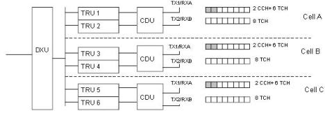
- Antenna Configuration top view (with duplex filter)
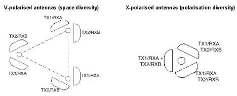
2. Frequency Allocation
Since an operator only has access to a limited number of frequency carriers, the frequencies have to be reused in the network. In order to prevent co-channel interference (C/I), the frequencies are reused in an organised way, according to certain re-use pattern.
Example: a reuse-factor 3.

The distance D between two cells using the same frequencies must be long enough to ensure that C/I is superior to a certain threshold. With a reuse factor 9, C/I will be superior to 9 dB; with reuse factor 12, C/I > 12 dB and with reuse factor 21, C/I > 18 dB. If we use 3-sector sites, the corresponding cell patterns are called 3/9 (3 sites/9 cells), 4/12 and 7/21. The figure below shows 4/12 and 3/9.
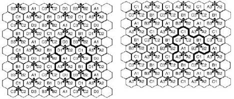
Ericsson recommends (C/I)min = 18 dB for analog systems (NMT, TACS) and 12 dB for GSM. But 9 dB is acceptable if interference-reducing features are used (such as frequency hopping, DTX, MS/BTS power control). This means that a 4/12 pattern must be used for BCCH carriers (which cannot use features such as fhop, DTX, pwr ctrl). However, the other carriers can have tighter reuse factor such as 9 or less. This is called Multiple Reuse Pattern (MRP).
Example MRP :
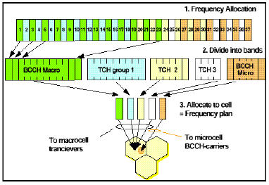
The operator has 37 frequencies. BCCH carriers have a frequency reuse factor 12. The second TRX in each cell have a frequency reuse-factor 8, the third have a reuse-factor 6 and the fourth have a reuse-factor 4.
3. Cell Capacity
Cell planning begins with traffic and coverage analysis. The analysis should produce information about the geographical area and the expected capacity (traffic load). The types of data collected are:
- Cost
- Capacity
- Coverage
- Grade of Service (GoS)
- Available frequencies
- Speech quality
- System growth capability
The basis for all cell planning is the traffic channel demand, i.e. how many subscribers use the network and how much traffic they generate. The Erlang (E) is a unit of measurement of traffic intensity. It can be calculated with the following formula.
A = n x T/3600 Erlang
Where,
A = offered traffic from one or more users in the system
n = numbers of calls per hour
T = average call time in seconds
The geographical distribution of traffic demand can be calculated by the use of demographic data such as:
- Population distribution
- Car usage distribution
- Income level distribution
- Land usage data
- Telephone usage statistics
- Other factors like subscription/call charge and price of MSs.
Calculation of required number of BTSs.
To determine the number and layout of BTSs the number of subscribers and the Grade of Service (GoS)have to be known. The GoS is the percentage of allowed congested calls and defines the quality of the service.
If n = 1 and T = 90 seconds the traffic per subscriber is:
A = 1 x 90/3600 = 25 mE
If the following data exist for a network:
- Number of subscribers = 10000
- Available frequencies = 24
- Cell pattern = 4/12
- Gos = 2%
- Traffic per subscriber 25 mE
This lead to the following calculations:
- Frequencies per cell = 24/12 = 2
- Traffic channels per cell = 2 x 8 – 2 (control ch.) = 14 TCH
- Traffic per cell = 14 TCH with a 2% GoS implies 8.2 Erlangs per cell (use erlang table)
- The number of subscribers per cell = 8.2 E / 25 mE = 328 subscribers per cell
- If there are 10000 subscribers then the number of cells needed is 10000 / 328 = 30 cells
- Therefore the number of three sector sites needed is 30 / 3 = 10
Filed under: ERICSSON | Leave a comment »


 Jakarta Time